Faults represent anomalies in physical and software systems, subsystems, components, and parts. Engineers attempt to understand the impact of faults on their designs by modeling the faults in a process known as fault modeling. After modeling the faults, engineers perform fault injection to introduce their behavior into a system. Depending on where the fault is and the kind of behavior it injects, faults can insignificantly affect a product or cause total failure.
You can perform fault injection on your Simulink ® models by using Simulink Fault Analyzer™ . After you add faults to your models, you can adjust the behavior, control how they inject behavior, and simulate their impact on the model.
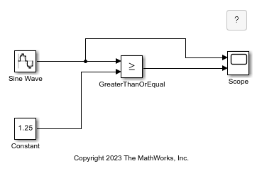
This example takes a sine wave and checks when it is greater than or equal to 1.25 . You can view the simulation results in the Scope block. The model does not include faults. Open the model to get started.
![]()
Open the Fault Analyzer app. In the Simulink model, in the Apps tab, click Fault Analyzer. Next, add a fault to the model. In the model, click the Sine Wave block output signal. In the Fault Analyzer tab, in the Prepare Faults section, click Add Fault. Alternatively, you can click a signal, point to the ellipsis to open the action bar, and click the Add a fault on the signal icon . The Add Fault window displays the properties you can assign to the fault.
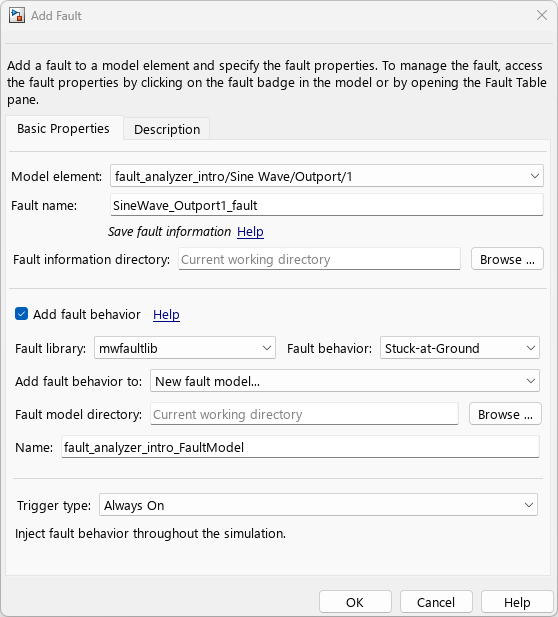
When you add a fault, select the model element by specifying the Model element property. You can select block input or output ports connected to the signal. If you select an input port, the fault modifies the signal just before it enters the block. If you select an output port, the fault starts at the output signal of the Simulink block and propagates downstream until the signal encounters another block. In this example, assign the fault to the output port of the Sine Wave block by setting Model element to fault_analyzer_intro/Sine Wave/Outport/1 .
Simulink Fault Analyzer comes with a list of built-in example fault behaviors. Access these example behaviors by selecting mwfaultlib from the Fault library property. You can use these fault behaviors as-is for scalar double signals. If your signal is a different type, you may need to create custom behaviors instead. For more information on predefined and custom behaviors, see Create Predefined and Custom Fault Behaviors.
![]()
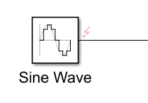
After selecting the library, you can select a fault behavior by setting the Fault behavior property. In this example, add a fault with noise behavior. Set Fault behavior to Add Noise and click OK. After you add a fault, the fault badge appears next to the signal.
When you add the first fault to a model element, Simulink Fault Analyzer creates an XML file that contains fault information for the model. This file is called the fault information file. Each model uses one fault information file. By default, Simulink Fault Analyzer saves the fault information file in the current working directory. You can specify a different directory for the fault information file when you add the first fault to your model. In the Add Fault window, specify the directory in the Fault information directory property. Additional faults automatically use the same fault information file.
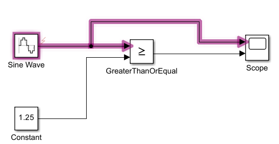
You can highlight faults to visualize the affected model elements and signals. To turn highlighting on or off, in the View section, click Highlight Faults.
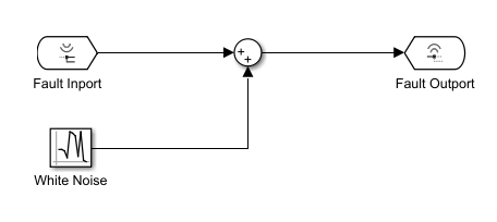
To model fault behaviors, Simulink Fault Analyzer uses blocks in subsystems that are separate from your design. In this example, open the fault behavior for SineWave_Outport1_fault . Click the fault badge. Click on the preview window. The fault behavior assigned to this fault uses a White Noise block to add noise to the signal.
Simulink Fault Analyzer stores the assigned fault behavior in a separate SLX file called the fault model. If you add fault behavior to a fault, the software adds an instance of the fault behavior to the fault model in a Fault Subsystem block. You can view the fault model by navigating to the parent model of the subsystem or by directly opening the fault model. You specify the directory that the fault models is saved in the Fault model directory property in the Add Fault window. By default, the fault model uses the name of the file and appends it with _FaultModel . In this example, that file is fault_analyzer_intro_FaultModel .
You can add multiple faults to a block output signal. Add another fault to the output signal of the Sine Wave block. The default name for this fault is SineWave_Outport1_fault_1 . For this example, do not edit the fault name. Set the Fault behavior property to Gain . Click OK. Save the new fault by saving the model, or by clicking Save All in the Fault Analyzer tab, in the File section. If you attempt to close the model without saving, Simulink displays a dialog box that prompts you to save the fault model and fault information file before closing.
To delete a fault:
![]()
Deleting faults also deletes the associated fault behavior in the fault model. If you delete a fault and the fault behavior is the only one in the fault model, you also delete the fault model.
You can also delete a fault by deleting the associated model element.
Faults cannot inject their behavior into the model until you enable their assigned model element. Once you enable a model element, you then must select the fault that you want to inject. The fault that you select is the active fault. At least one fault is active on each enabled fault element. Consequentially, if you only have one fault on an enabled model element, the fault is automatically active.
You can enable model elements and activate faults by accessing the fault properties. To access the properties of the faults on the Sine Wave block:
![]()
To adjust the properties of a fault, select the fault from the Select fault to view property. For more information, see Specify Fault Properties.
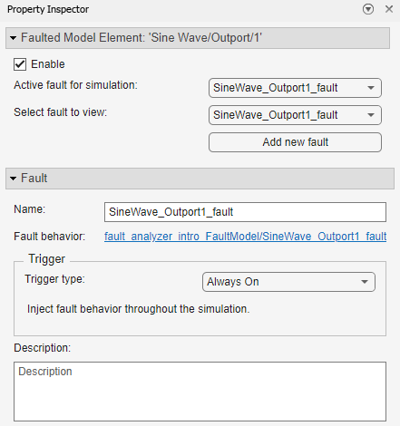
Enable faults on the block output signal by selecting Enable. If faults are enabled on the signal, you can select one active fault for a model element. In the Property Inspector , select SineWave_Outport1_fault as the active fault from the Active fault for simulation property. To disable the faults on a single model element, clear the Enable property. If you want to activate a different fault, select the fault in the Active fault for simulation property.
When you enable faults on a model element and select an active fault, Simulink Fault Analyzer does not inject the behavior to the model during simulation until specific conditions occur. You specify these conditions for each fault with a trigger. If the trigger conditions are met, the fault behavior is injected into the model. To control how a fault triggers, adjust the trigger for the fault with the Trigger type property.
For this example, set SineWave_Outport1_fault to trigger after five seconds of simulation time. To do this, change the Trigger type to Timed and enter 5 in the Trigger fault at time property.
You can use the Fault Table pane to view and select faults in your model. By default, the Fault Table pane opens at the bottom of the Simulink Editor when you select Fault Analyzer in the Apps tab. If you close the Fault Table pane, you can open it again by clicking Fault Table in the Fault Analyzer tab.
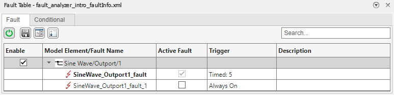
The pane shows the model elements that contain faults, the faults associated with each model element, the activation status of the faults, and whether the model element is enabled. You can use the pane to view and manage faults:
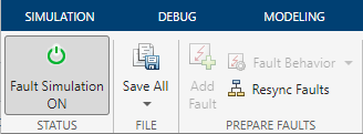
To allow fault simulation, you must turn it on. In the Fault Analyzer tab, in the Status section, click the Fault Simulation button. Fault simulation is on when the button is green and the status is on.
![]()
You can also enable fault simulation by pressing the Turn on/off simulation of faults button in the Fault Table pane.
Turn on fault modeling and click Run. Open the Scope block to view the effects of the fault. The Sine Wave block output now has noise when the time is 5 .

If you disable fault simulation, the Sine Wave block output returns to normal.
You can confirm that the fault injected by opening the Fault Dashboard tab (since R2024a) . In the Fault Analyzer tab, in the View section, click Fault Dashboard. The Simulation Results tab shows that the active fault, SineWave_Outport1_fault , triggered during the simulation.
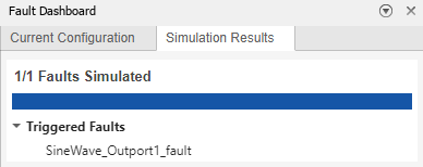
If the fault is not injected during simulation, the Triggered Faults section does not display it.
If you want to delete the faults and behaviors that you created without manually deleting each fault or model element:
Deleting these files permanently deletes the fault artifacts associated with the models that use the fault information file or fault model.
Run the command by entering it in the MATLAB Command Window. Web browsers do not support MATLAB commands.
Select a Web Site Choose a web site to get translated content where available and see local events and offers. Based on your location, we recommend that you select: .
You can also select a web site from the following list:
Select the China site (in Chinese or English) for best site performance. Other MathWorks country sites are not optimized for visits from your location.